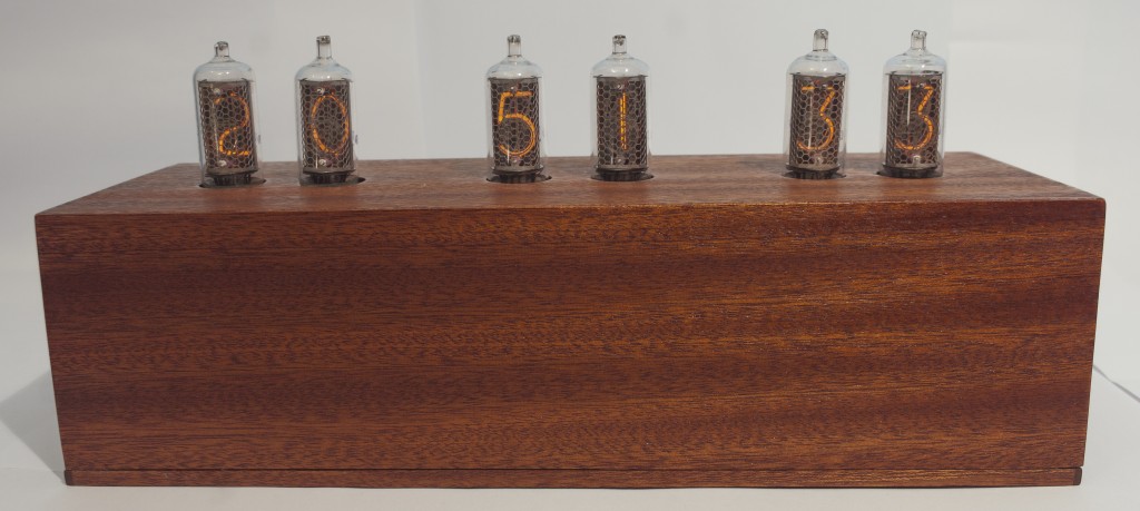
Nixie clocks are really beautiful pieces of equipment, but interfacing high voltage (250 VDC) obsolete components with 5 V microcontrollers is not an easy task. I came across many designs on the internet that use obsolete chips to solve this problem, but these chips are expensive and really hard to find. My design uses no obsolete components, except for the Nixie tubes, of course.
Main board
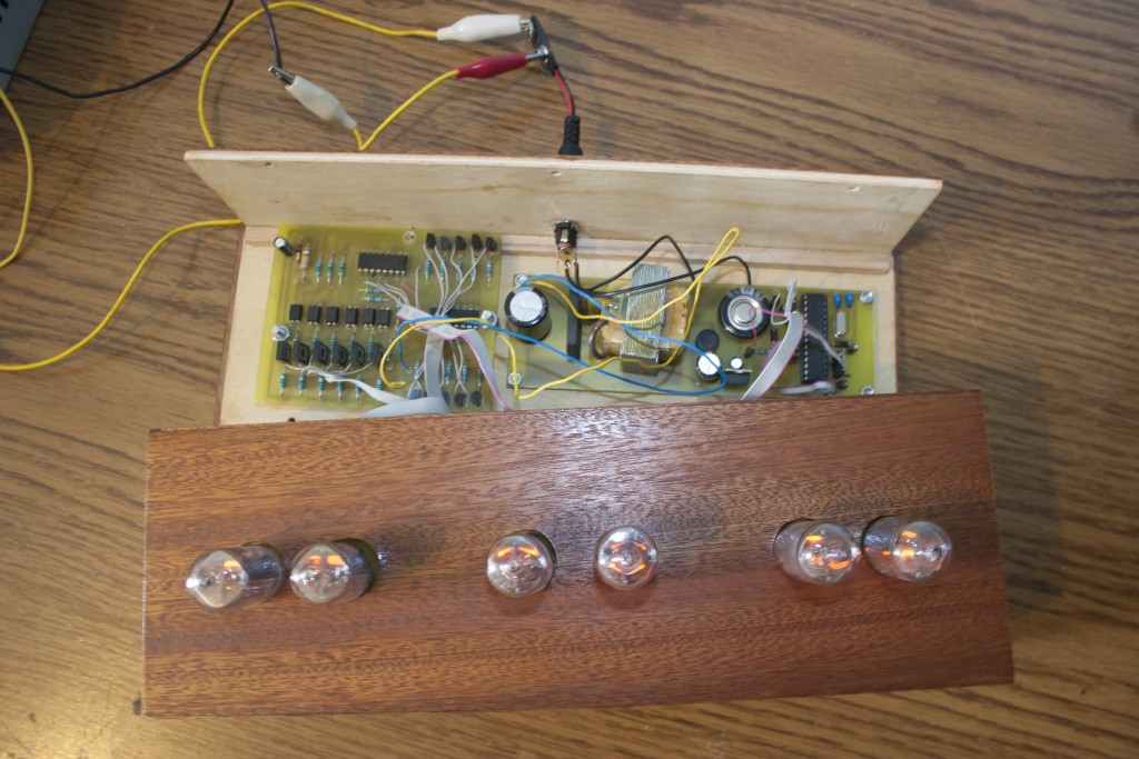
The main board is based on the Atmel ATMEGA328P-PU microcontroller. The code was written in Arduino IDE and an Arduino UNO was used for programming the microcontroller. The date and time are set using three buttons (Set, +, -). The clock also has a RTC ( DS3231 ) that keeps running when the clock loses power. It uses a supercapacitor that is charged while the clock is plugged in. (it works about a month without external power)
Power supply
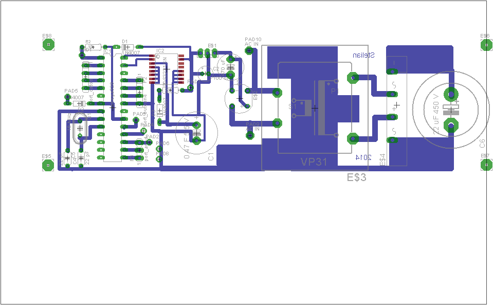
The power supply consists of a 9 VAC wall adapter, a small 12 V – 220 V transformer (used to step up), a rectifier bridge and filter capacitor for the anode voltage and another rectifier bridge, filter cap and 7805 regulator for the microcontroller, RTC and the driver.
Nixie driver
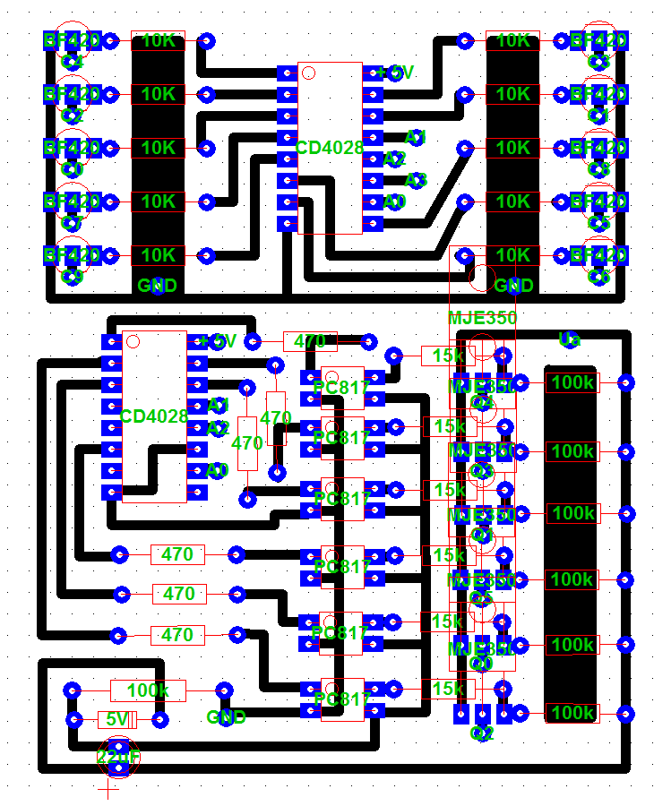
The data from the microcontroller comes as BCD (parallel). There are 4 wires that select which digit is to be displayed that go into a BCD decoder, then to the cathodes of the tubes through the cathode output stages that use one NPN transistor each. Since the tubes are multiplexed, all the corresponding cathodes are wired in parallel. The tubes are powered one at a time but because the refresh rate is high enough they look like they are permanently turned on. In order to select which tube is on I used the same principle as for the cathodes, but the output stages are different because the PNP transistors are on the hot side (250 V to the emitters). I used optocouplers to drive the PNP transistors.
The code
Note : The microcontroller runs Arduino code although it does not have an Arduino bootloader on it. (the bootloader is not needed)
The code first checks if there is valid date and time data in the RTC. If data is found, the Time library gets the time from the RTC, then the clock starts running. If no data is found, the tubes display “00” and the user should set the time using the buttons. (time is set on both the microcontroller and the RTC, of course) The microcontroller also updates its time from the RTC once a day because it is less precise than the temperature compensated RTC.
Time is displayed by first turning on one of the NPN (cathode) transistor through the decoder. Then, the corresponding tube is powered for a short period of time by applying 250 V to its anode through the decoder and the anode output stage. Then the algorhythm moves to the next tube and so on and cycles through all tubes in order to make them appear turned on continuously. This is done because you cannot turn multiple tubes on while they’re multiplexed. (google multiplexing for more detail) Once every 20 seconds the time shifts left one digit at a time and then the date shifts in from the right and stays for a few second, then the clock displays time again.
You can post my designs anywhere else as long as you provide a link to the original source or metion me as the author.
The project files are available on my github account.
Contact : Stelian Saracut – stelian at saracut dot ro


 re compared and in case of collision the alive variable is set to false and procedure dead is called which makes the chip fall. The chip is not allowed to hit the margins of the screen so if that happens it is considered ,,dead” as well. Finally, the score is incremented as each pair of tubes is avoided, the chip’s vertical position is incremented (so that it falls unless you press the button) and the delay keeps the game from running at lightning speed (or not really, with only 16 MHz clock speed). After the gameloop, the button interrupt is detached and the score is compared to the highscore (if there is one in the EEPROM). If there is no highscore, or your current score is higher than the highscore, a new higscore is written in the EEPROM so that it will not be lost when the MCU loses power. And just in case you become addicted to this game, you don’t have to worry about EEPROM wear out because a memory wear leveling algorithm writes the highscore at a different adress each time.
